


Tone control circuit.
This is just another circuit designed by Mr. Seetharaman Subramanian and time it is a high quality passive tone control circuit that has an overall gain of around 25 with 20dB boost and cut. This circuit needs minimum number of components, is very cost effective and most of the components required can be found from you junk box. Even though an opamp which is an active element is used in the circuit, the tone control section is entirely passive and that’s why the circuit is named so.
Description.
The circuit consists of two parts. Firstly an op-amp based preamplifier stage and secondly a passive Baxandall tone control circuitry. The preamplifier stage is a non inverting amplifier based on TL072. R2 is the feedback resistor which together with resistor R1 sets the gain of this stage and with the stated values it is 23. Voltage gain in the non-inverting mode is expressed using the equation Av= 1+ (R2/R1). Value of R3 (Rin) is taken as approximately equal to the output impedance of TL072. C2 is the input DC decoupling capacitor and it also sets the low frequency cut off limit. R4 is the offset minimizing resistor which reduces the effect of output offset voltage on the output of the amplifier and its value is taken as approximately equal to R1||R2. The preamplifier stage is powered using +15/-15 dual supply. Capacitor C3 couples the preamplifier stage with the tone control stage.
The tone control stage is a passive Baxandall tone control circuit that can produce a 20dB cut or boost. POT R6 is used for controlling the bass while POT R9 can be used for controlling the treble. POT R10 serves as the volume controller while POT R11 can be used to adjust the balance. Resistor R8 provides some isolation between the bass control and treble control stages.
Passive Baxandall tone control circuit: Also known as James Network is a circuit for independently adjusting the bass and treble for high quality audio applications. The circuit is entirely based on passive components and the performance is very superior. In many older passive tone control circuits there was much interaction between the two controls and there was a great deal of asymmetry. Such problems are completely eliminated in Baxandall tone control circuit.
Circuit diagram.
 Passive tone control circuit
Seetharaman’s words about the circuit: Iam just enclosing you the TL072 (TL062 or 82 also can be used) passive tone control with 20dB boost and cut with a overall gain of around 25. you can also give an overall feedback if required, from output to TL072 inverting input through suitable resistance.
Dual supply for this circuit.
A +15V/-15V dual supply for powering this tone control circuit is shown below. Bridge D1 can be made using four 1N4007 diodes. This supply is unregulated and its quite fine for this circuit. Anyway if you need to have a regulated one please inform me.

Power supply for tone control circuit
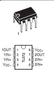
TL072 pin out
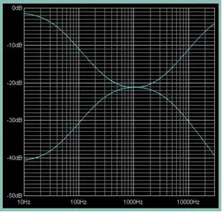
Frequency response plot
Notes.
- Circuit can be assembled on a vero board or perf boad. Any way a PCB is the best option.
- Use +15/-15V DC dual supply for powering the circuit.
- IC1 TL072 must be mounted on a holder.
- By changing the value of R1 and R2 the voltage gain (Av) of the preamplifier stage can be changed.


