


Team Agnirath from IIT Madras
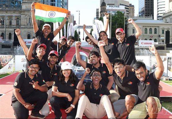
Team Agnirath(agnirath.in) from IIT Madras is a dynamic group of 48 undergraduate students passionate about solar car racing and sustainability. We made history last year by becoming the only Indian team to compete in the World Solar Challenge 23 and now are focused on making our upcoming car which aims to dominate the 2025 World Solar Challenge.
We aim to design and build a high-performance solar car optimized for Australia's harsh conditions. Our multidisciplinary approach involves the mechanical team focusing on cooling systems, aerodynamics, suspension, and vehicle dynamics. The electrical team is dedicated to developing efficient battery packs, integrating solar panels, and ensuring seamless circuit connectivity. Leveraging advanced tools we conduct thorough analyses and simulations to refine our designs. Our business team secures sponsorships, manages finances, and handles PR activities to sustain and promote our project. Learning from past experiences, we continuously improve our designs, focusing on weight reduction, manufacturability, and optimal integration of all components. Our ultimate goal is to create a sustainable, efficient, and competitive vehicle for the World Solar Challenge 2025.
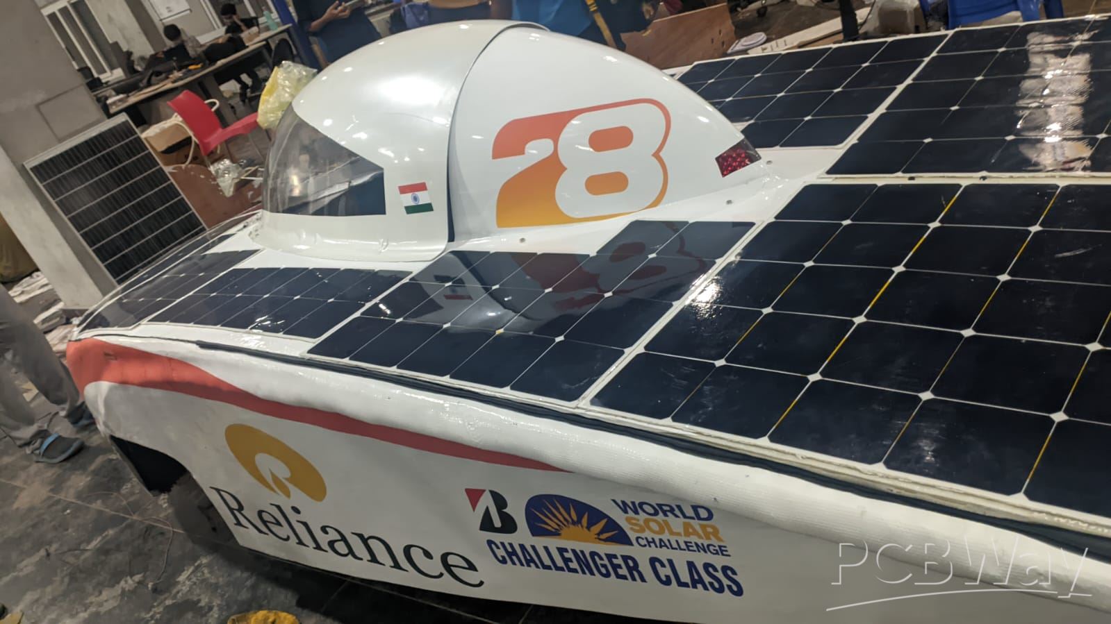
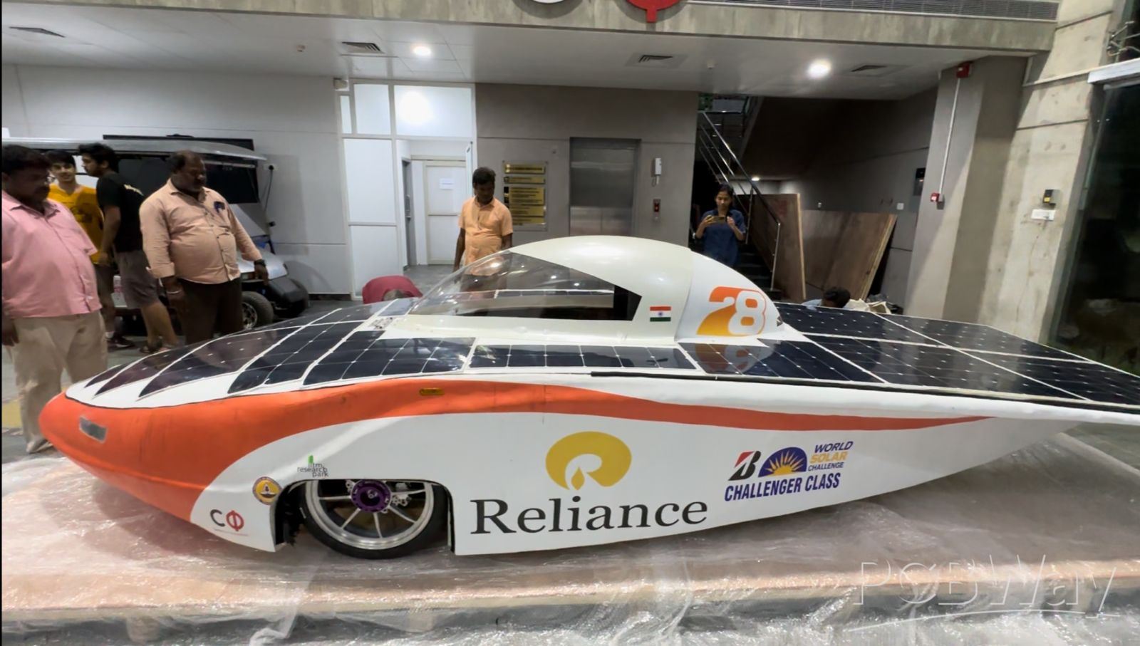
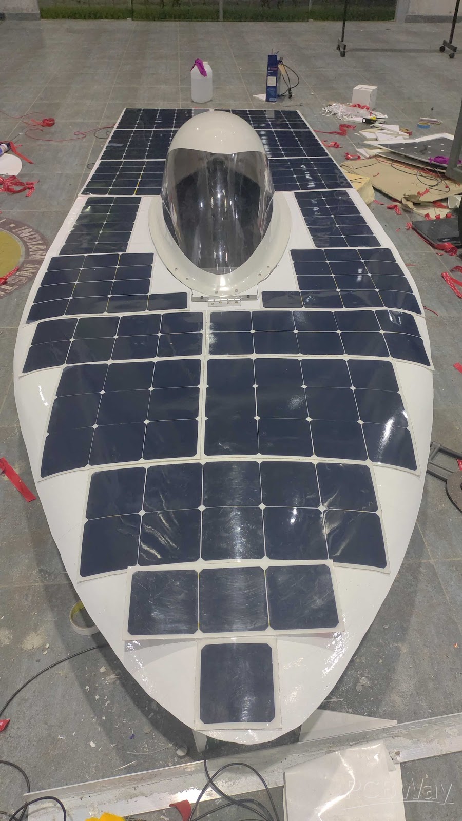
Pictures of our car Aarush-
Part of our project that uses PCBs extensively are:
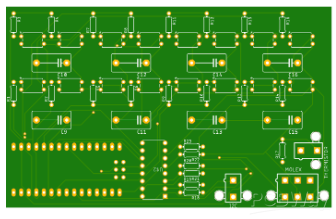
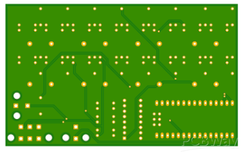
1. Battery (Active balancing CMU-I)
This is the PCB that we are working on, this applies the principle of active cell balancing for the cells. It has a variety of components such as Opto relays, MCP3208, Capacitors, Molex connectors, Resistors, and Arduino nano.
The cell input directly charges the lower series of capacitors; the Arduino then turns on the first lower series of opto relays to connect these capacitors to the upper capacitors. Once the upper layers are charged the upper series of opto relay turns on, to connect these capacitors, and balancing of voltage occurs. Then again the reverse cycle goes on, the upper capacitors then charge the lower capacitors which then charge the cells and balance them. The ADC actively notes the cell potential and stops when required.
2. Motor Interface Board
The motor interface board is used to communicate data from the hall effect sensors on the motor to the motor controller. There are two types of hall effect sensors, i.e., position sensor and temperature sensor. Determining the position of permanent magnet poles on the rotor is vital so that the controller knows which stator coils to energize at any given instant of time. The motor has 3 hall effect position sensors and each has been designated one channel on the motor sense interface. The position sense connector is a 6-pin Molex Microfit connector.
The temperature sensor has been designated one channel and an NTC (negative temperature coefficient) thermistor is used for detecting the motor temperature. The stator coils must not go beyond a certain temperature threshold otherwise the motor will get damaged and stop working. The motor current is reduced if the temperature rises. The temperature sense connector is a 2-pin Molex Microfit connector.
The connector between the interface board and motor controller is a 14-pin Molex Microfit Connector. Also, the signal inputs for this connection are differential. The communication between the interface board and motor controller is carried out using the UART protocol.
3. System Controls - MAIN PCB
The main PCB helps the Jetson Orin connect to the CAN bus, allowing a pathway for the Jeston to control all the Lamps of the car and help the Orin connect to other modules of the car such as the telemetry module, GPS module, and cameras. The other modules include Telemetry, GPS, camera, driver's interface module, and possibly a new module to track windspeed, crosswinds, angle of incidence of light, and monitoring of a single solar cell. All these would be connected to the Main PCB via USB ports and Can.
4. Driver's Interface
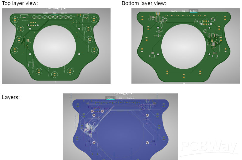
(i)Steering PCB
It transfers the input given by the user to the system to operate according to what the driver wants. The input includes left and right Indicators, Horn, speed, the torque of the motor, acceleration of the car, Cruise mode, etc.
(ii)DCU
A Driver Control Unit (DCU) is the main feeder of the signal in the can network as it sends the message that the driver gives to the respective controllers. The main function of this PCB is to send instructions to BMU about the current state and if there is any change of state as given by the driver.
We need PCBWay's support to create and design more effective PCBs that can help our electrical module to make our cars run more efficiently thus contributing to the future technology of sustainable mobility. We are looking forward to your positive response to collaboration.
Thank you!
- Comments(0)
- Likes(2)


