Overview:
In this project we are going to learn how to build an infrared based non-contact thermometer which can be utilized for screening people at schools, offices, shopping malls etc. for abnormal body temperature which could be a sign of contagious diseases.
The proposed non-contact thermometer can measure body temperature of a person at forehead and records it in a text file on a SD card with time and temperature. If a person has abnormal body temperature the machine will alert by beeping.
Non-contact thermometers are best for measuring body temperature quickly and accurately for initial temperature screening of a person. Unlike contact based thermometers, non-contact based thermometers carry very low risk of spreading communal disease while utilizing it, which makes it very suitable for mass screening of hundreds or even thousands of people quickly.
Circuit Diagram:

Circuit description:
The proposed circuit consists of the following components and can be assembled on a PCB for reliable operation:
Let’s take a brief look at each modules presented in the project.
MLX90614 non-contact temperature sensor:

MLX90614 is an IR based non-contact temperature sensor, which is heart of this project. The sensor can measure temperature of an object between -70 degree Celsius and +380 degree Celsius, which is more than enough bandwidth for our project, the sensor can operate at ambient temperature between -40 degree Celsius and +125 degree Celsius.
MLX90614 can operate between 3.3V and 6V if your sensor comes with a breakout board as illustrated in the above image, because the breakout board comes with a voltage regulator. MLX90614 sensor works on I2C bus which makes interfacing with Arduino easy and it can be done by just hooking up the SDA and SCL lines to Arduino.
The effective measuring distance between an object and the sensor is only few centimeters, to make this sensor operate in real-life situations we need to increase its range by calibrating / compensating the received raw temperature value from the sensor (in the program code). We will try to understand this in the later part of this post.
SD card module:

Generally, interfacing a micro SD card directly with any microcontroller is technically challenging, a micro SD card adapter module such as one illustrated above makes it easy.
This SD card adapter module regulates correct supply voltage and signal voltage to the SD card. This module consists of 3.3V on-board regulator and a level shifter IC which is responsible converting 5V signal from Arduino to 3.3V signal to SD card.
This module communicates with Arduino via SPI protocol and we need to establish four communication lines between Arduino and this SD card module which are MISO, MOSI, SCK and CS.
Real Time Clock Module:

The proposed project utilizes a RTC module DS3231 or DS1307 (both are compatible) for registering correct time with the temperature when a person scans his/ her body with this machine.
The RTC module is responsible for tracking the correct time, it also comes with a backup battery which will keeps the RTC running even when the main power supply is disconnect.
The RTC module works on I2C protocol similar to the temperature sensor and also connects with the same bus wire.
How to set time to RTC:
Ultrasonic sensor:

An ultrasonic sensor is employed in the project to measure the distance between MLX90614 sensor and a human subject. A temperature reading is captured when the human subject is at the correct distance.
The distance at which a temperature measurement is captured is between 12.5 cm to 14 cm (from the sensor). So, when someone brings their forehead towards the temperature sensor, it will capture a reading between these two fixed points.
There is a need for measuring the temperature at a fixed distance, because MLX90614’s temperature value varies as the distance between the sensor and subject changes.
The MLX90614 must be mounted close to the ultrasonic sensor to get reliable temperature reading as illustrated in the above image.
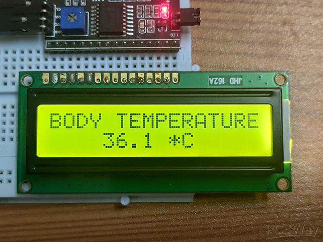
I2C LCD Display:

We are using an I2C display adapter module to reduce the number of wires that connects from Arduino to LCD so that we can build the circuit with ease. We just need to connect four wires: SDA, SCL, Vcc and GND otherwise we will be connecting 16 wires.
Use a Phillips screw driver to adjust the contrast of the display and connect the jumper to enable backlight for the LCD.
Buzzer:
A 5V DC buzzer is utilized in this project to alert a high body temperature with beeps and also to give user feedback that a temperature reading has been captured by the sensor.
When a temperature reading is capture the buzzer produces a short beep. When a temperature reading is more than the threshold temperature that you have set in the code, the buzzer beeps for 5 seconds. When the body temperature is less than the threshold value, buzzer won’t beep, except the short beep while capturing a measurement.
Program code: https://github.com/Electronics-Project-hub/Contactless-Thermometer/blob/main/Contactless_Thermometer.txt
Prototype image:


Temperature calibration:
After you build the circuit the next step is to calibrate the machine for capturing correct temperature. This can be done by following the below given steps and you need an IR thermometer gun as a reference thermometer:
1) Upload the code with following parameters:

Set “calib_factor” to 1.00 and “alert_temp” to 37.0.
2) Gently move your forehead towards the sensor and take 5 temperature readings.
3) Now take 5 temperature readings using IR thermometer gun.
4) Now calculate the mean of the temperature reading from the circuit and mean of the temperature reading from IR thermometer gun.
(Temp1 + Temp 2+ …….Temp 5) / 5 = Average value
5) Now divide both the mean value as shown:
Avg. IR thermometer value / Avg. temperature value of machine = Calibration factor
6) Now enter the calculated calibration factor to the variable “calib_factor” in the program code and upload.
7) Now take few readings using the circuit and the readings from the display will be close to IR thermometer gun.
8) Now your machine is ready to use and each temperature reading is logged in a text file in the SD card as shown below:

Note: The content and the pictures in this article are contributed by the author. The opinions expressed by contributors are their own and not those of PCBWay. If there is any infringement of content or pictures, please contact our editor (steven@pcbway.com) for deleting.
Written by Blogthor.


