By Hesam Moshiri, Anson Bao
Features
High stability and no sensitivity to the ambient light
Laser-cut acrylic (plexiglass) enclosure
Cost-effective
Flow control capability of the hand-sanitizer/alcohol (efficiency)
Through-hole components (easy to solder)
Single-layer PCB board (easy to fabricate)
Single and cheap ATTiny13 microcontroller
Low standby current consumption
As we all know, the COVID-19 outbreak hit the world and changed our lifestyle. In this condition, alcohol and hand sanitizers are vital, expensive, and in some areas hard to find fluids, so, they must be used properly and efficiently. In the second version of the hand sanitizer dispenser device, I have addressed the previous design problems and introduces a device with no sensitivity to the ambient light and flow control capability of the alcohol/sanitizer. Therefore just enough amount of liquid will be poured on each request. The design uses a cheap ATTiny13 microcontroller.
[A] Circuit Analysis
figure 1 shows the schematic diagram of the device. The task could be fulfilled by a variety of sensors and design methods, however, my focus was to design an efficient, cheap, and simple circuit.
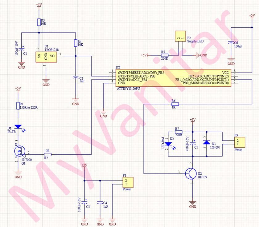
Figure 1
Schematic diagram of the automatic hand sanitizer dispenser
P2 is a 2-pin male XH connector. It is used to connect a 5mm blue LED that should be mounted on the enclosure and the hand sanitizer/alcohol container. R5 limits the LED’s current.
U1 is the TSOP1738 [1] or HS0038 IR receiver module. It is a complete unit that is used for detecting and decoding IR signals. Figure 2 shows the block diagram of this component.
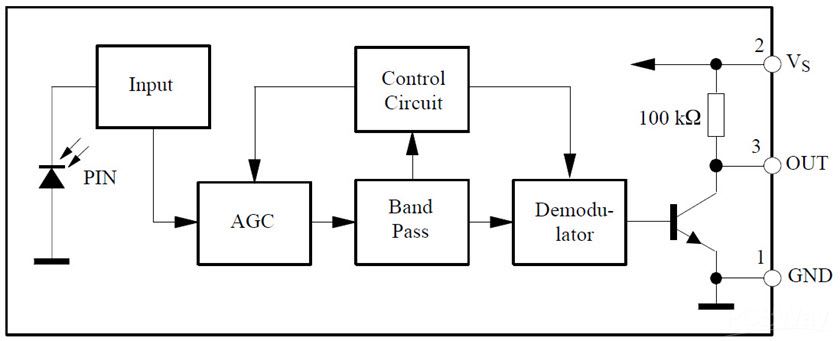
Figure 2
Block diagram of the TSOP1738 (HS0038) IR receiver module
The module can accept 5V at the supply rail and it consumes around 5mA. Low current consumption of the component allows us to use a simple RC filter (C1 and R3) to eliminate possible instabilities (false IR signal detection) that might be introduced by the supply noise.
The cut-off frequency of the above-mentioned RC filter can be both simulated (such as LTSpice) or examined in practice. To test the filter’s behavior in practice, I used a Siglent SDS1104X-E oscilloscope and a Siglent SDG1025 waveform generator. These two devices must be connected using a USB cable. Figure 3 shows the bode plot of the filter’s behavior. The calculations confirm that the cut-off frequency of the filter is around 112Hz in practice. For more details please watch the video.

Figure 3
Testing the RC filter’s behavior in practice by bode plot and the SDS1104X-E oscilloscope
R4 is a pull-up resistor and C2 reduces the U1 output noises. D1 is a 5mm IR transmitter diode and R1 limits the current to the diode. The R1 value could be in the range of 150R to 220R. Lower resistance means higher detection range and vice versa. I used a 180R resistor for the R1. Q1 is the 2N7000 [2] N-Channel MOSFET that used to switch ON/OFF the D1 IR diode. R2 limits the gate’s current.
IC1 is the ATTiny13 [3] microcontroller. It is a known and cheap microcontroller that provides adequate peripherals for this application. PORTB.4 generates a square wave pulse for the IR transmitter diode and PORTB.3 senses the activate-low signal. PORTB.1 used to send the activation signal to the pump. The duty cycle of this single pulse defines the flow of alcohol or hand sanitizer.
Q2 is the BD139 [4] NPN transistor that used to switch ON/OFF the pump. D3 eliminates the reverse inductor currents (DC motor of the pump) and C5 reduces the pump noises. D2 indicates the pump activation. R7 limits the LED’s current.
C3, C4, and C6 used to reduce the supply noises.
[B] PCB Layout
Figure 4 shows the PCB layout of the automatic hand sanitizer dispenser. It is a single-layer PCB board and all component packages are through-hole.
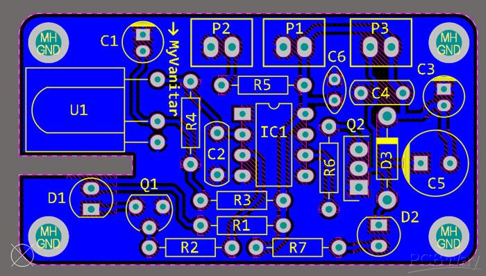
Figure 4
PCB layout of the automatic hand sanitizer dispenser device
I used the SamacSys component libraries for Q1 [5], Q2 [6], and IC1 [7]. The SamacSys libraries always help me to avoid unwanted mistakes and bypassing the time-consuming process of designing the component libraries from scratch. There are two options to install and use the libraries. First, downloading and installing them from componentsearchengine.com or second by installing them directly using the provided CAD plugins [8]. SamacSys has provided plugins for almost all electronic designing CAD software. In my case, I used the Altium Designer plugin (Figure5).

Figure 5
The selected components in the SamacSys Altium Designer plugin
Figure 6 shows a picture of the first working prototype of the hand sanitizer dispenser board. Do you see the cut-out in the PCB board? It is necessary to prevent any unwanted IR signal reception by the U1 module. This gap gets filled with a piece of the enclosure.

Figure 6
The first working prototype board of the hand sanitizer dispenser
[C] Source Code of the Microcontroller
The code has been written in C. The important part of the code which you “might” need to modify is the Timer-0 overflow interrupt routine.:
interrupt [TIM0_OVF] void timer0_ovf_isr(void)
{
if (PINB.3 == 0 && activated == 0)
  activated = 1;
if (activated == 1)
 counter ++;
switch (counter)
{
  case 15:
   PORTB.1 = 1;
  break;
   case 23:
   PORTB.1 = 0;
  break;
   case 372:
   counter = 0;
   activated = 0;
   break;
}
}
“case 15” defines the preactivation delay. A short delay is necessary for the user to fix his hand below the sensor and nozzle. “case 23” defines the pump activation time and “case 372” defines the delay before the next possible activation. This delay allows enough time for the user to gather all hand-sanitizer/alcohol drops. Also, it prevents misusing the device and wasting the expensive liquid by children or some individuals.
Fusebits must be set on the 9.6MHz internal clock source with no clock division.
[D] Laser-Cut Corel Draw Enclosure Design
Figure 7 shows the designed enclosure in Corel Draw. You just need to send the “sanitizer.cdr” file to a laser-cutting workshop/company and order the laser-cut for 2mm matt black plexiglass (acrylic). Thin plywood is also okay.

Figure 7
The hand sanitizer dispenser enclosure design in Corel Draw
Figure 8 shows the complete automatic hand sanitizer dispenser unit. You can mount the enclosure on your desired container. I used a glass container.

Figure 8
Automatic hand sanitizer dispenser with a glass container
[E] Bill of Materials

PCB Layout: Download the Gerbers or order the PCB for fabrication
Enclosure: Download here
Source Code: Download here
[F] References
[1]: TSOP1738 datasheet: https://www.batronix.com/pdf/tsop17xx.pdf
[2]: 2N7000 datasheet: https://www.onsemi.com/pub/Collateral/NDS7002A-D.PDF
[3]: ATTiny13 datasheet: https://componentsearchengine.com/Datasheets/1/ATtiny13-20PU.pdf
[4]: BD139 datasheet: https://www.st.com/resource/en/datasheet/bd140.pdf
[5]: 2N7000 schematic symbol and PCB footprint: https://componentsearchengine.com/part/1011182/model/download
[6]: BD139 schematic symbol and PCB footprint: https://componentsearchengine.com/part/1041398/model/download
[7]: ATTiny13 schematic symbol and PCB footprint: https://componentsearchengine.com/part/235118299/model/download
[8]: CAD Plugins: https://www.samacsys.com/library-loader-help
https://componentsearchengine.com/part/1011182/model/download


