


|
KiCADKicad
|
Breakout Board for 3PDT footswitch and Jacks for 1590B enclosure
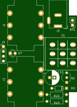
When I was designing my overdrive pedal, I wanted an easier way to assemble it. I find it way easier to solder components onto a PCB than using wires. And to minimize number of wires, I created a board that has support for Guitar in and out jack, barrel jack for 9V power, 3PDT foot switch, LED indicator and reverse polarity protection. Oh yes, and the battery support, but in the end, whether battery can be fit depends on the size of the effect board.
This is universal kind of a board so it can be used with any other effect that you might want to use - so in your case, you might be able to fit the battery. You could also use 12V, 18V (negative center) power supply if your effect can take it.
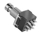
For this project I decided to go with a screw-on top jacks, they fit perfectly into Hammond 1590B type of an enclosure. Since the board is specifically designed for 60mm width enclosure, you won't be able to use it with anything else.

There are 4 wires there for connection with your effect board: In, Out, + and - ... probably self explanatory. In should go to Effect In, Out should be connected to Effect Out and + is for your 9V power supply of the effect board, and - is ground.
3PDT switch is wired so "Effect In" is grounded when the effect is disengaged.
Reverse polarity is done using P-type MOSFET, so the voltage drop is minimal thus providing maximum headroom for the pedal. This can be simplified using a Schottky diode instead of the Q1 transistor, for example. In that case you don't need R20 & D8.
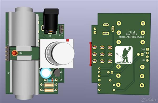
Here's the 3D view of the board and then the assembled board, they look pretty much the same - KiCad is awesome!!! :)

Just a note on this - drilling is critical. Everything needs to line up properly (well, that's sort of given when using a PCB version of an effect).
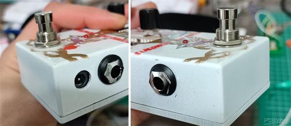
See the attachments, there's a drilling template in SVG format.
Here's the accompanying video:

Breakout Board for 3PDT footswitch and Jacks for 1590B enclosure
*PCBWay community is a shared platform and we are not responsible for any design issues.


- Comments(3)
- Likes(6)
- 1 USER VOTES
- YOUR VOTE 0.00 0.00

-
10design
-
10usability
-
10creativity
-
10content
More by Barbarach BC
-
 Breakout Board for 3PDT footswitch and Jacks for 1590B enclosure
When I was designing my overdrive pedal, I wanted an easier way to assemble it. I find it way easier...
Breakout Board for 3PDT footswitch and Jacks for 1590B enclosure
When I was designing my overdrive pedal, I wanted an easier way to assemble it. I find it way easier...
-
 Cliodhna - Queen of Screamers
I designed an overdrive pedal based on a Tube Screamer - but this one has 192 sound options!I chose ...
Cliodhna - Queen of Screamers
I designed an overdrive pedal based on a Tube Screamer - but this one has 192 sound options!I chose ...
-
-
Open Source Very Large Stick - Freejoy & MMjoy2 breakout board
573 0 0 -
RF Control training board for students based on ESP32 C3
766 0 2 -
-
KINETIC COASTERS with a TWIST! Laser or 3D Print some DIY Magic
658 0 1 -
RPI - 8 IO PLC With ATTiny85 Watch Dog
565 0 1 -
Nintendo Famicom HVC-001 Controller Shells
677 0 1 -
COMMODORE 128 DIAGNOSTIC REV.785260 KEYBOARD DONGLE
633 0 4


