


|
|
SI5351Silicom labs
|
x 1 | |
|
|
Arduino pro microArduino
|
x 1 | |
|
|
Display oled sh1106Display oled
|
x 1 |
Exploring the potential of the SI5351 module in electronic projects
In this tutorial, you will dive into the depths of this amazing device and discover its limitless potential in signal and frequency generation.
Join me as we explore all the functions and features of the SI5351 module, from its ability to generate multiple frequencies with amazing precision to its versatility in applications such as frequency synthesizers, software-defined radios, and communication projects.
Whether you are a beginner or a subject matter expert, this comprehensive guide will provide you with the knowledge to master the SI5351 module. You will learn how to configure it, control it through an arduino and take full advantage of its capabilities.
It doesn’t matter if you are interested in electronics, hobby radio or just exploring new technologies, this video will show you how the SI5351 module can supercharge your projects and take your creativity to the next level.
Get ready to immerse yourself in an exciting journey of discovery and learning. Don’t miss this opportunity to unlock the full potential of the SI5351 module!
Electronic components
Arduino Pro Micro
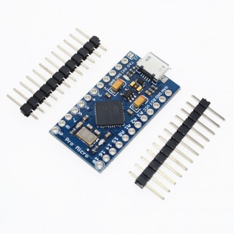
The Pro Micro is similar to the arduino Mini Pro except with an ATMEGA32U4 on board. This chip makes a big difference since it can also be used as a human interface device. The USB transceiver inside the 32U4 allows us to add USB connectivity on board and do away with bulky external USB interface. This little board does all the Arduino functions you are familiar with: 4 channel 10-bit ADC, 5 PWM pins, 12 DIOs, as well as hardware serial Rx and Tx connections. Running at 16 MHz and 5 V. This little microcontroller can go anywhere. There is a voltage regulator on board so that it can accept a voltage of up to 12V.
12 digital I/O pins (5 PWM)
4 analog input pins (10 bit each)
Input voltage 5-12V (It has an internal regulator)
Output voltage: 5v
Maximum total output current 150mA
ATMega 32U4 running at 5V/16MHz
Supported under Arduino IDE v1.0.1
Micro-USB connector for programming
4 pines x ADC de 10 bits
Rx and Tx Hardware Serial Connections
12 digital inputs/outputs of which 5 can be PWM.
Dimensions: 3.31cm X 1.78cm
SI5351 module
PinOut
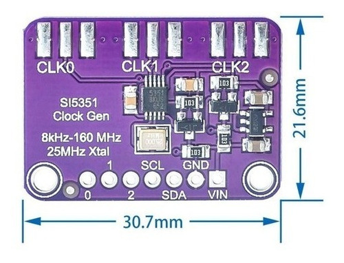
VCC: Power pin. It must receive a 3.3V or 5V power supply, depending on the module specification.
GND: Ground pin. It must be connected to the ground terminal of the system or power supply.
SDA: Bidirectional data line for I2C (Inter-Integrated Circuit) communication. This pin is used to send and receive data to and from the SI5351 module.
SCL: Clock line for I2C communication. This pin provides the clock pulse to synchronize data transmission between the master device and the SI5351 module.
CLK0, CLK1, CLK2: These pins are configurable clock signal outputs from the SI5351 module. You can use them to generate different frequencies and waveforms according to your needs.
MS0, MS1, MS2: These pins are register bank select pins for the SI5351 module configuration. They set the register bank that the I2C bus accesses.
The Si5351 is a Programmable Frequency Clock (PLL) generator produced by Silicon Labs. It is widely used in electronic projects and Radio Frequency (RF) applications, such as building oscillators, frequency synthesizers, software-defined radios (SDR) and other projects that require a highly accurate and stable signal source.
The Si5351 has the ability to generate three independent clock signals with frequencies ranging from a few kilohertz to a few hundred megahertz, making it suitable for a wide range of applications. In addition, it is programmable through an I2C communication interface, allowing designers to easily adjust the frequency and phase of the output signal accurately and quickly.
Clock Generator Si5351a – 8 Khz to 160 Mhz + 3 SMA female connectors
This module has a precision 25 MHz crystal reference and an internal PLL and dividers, so it can output almost any frequency from <8 KHz to over 160 MHz. The Si5351A Clock Generator is an I2C clock generator. It uses the onboard precision clock to control multiple PLLs and clock dividers using I2C instructions. By configuring the PLL and dividers you can create precise and arbitrary frequencies. There are three independent outputs, and each one can have a different frequency. Outputs are 3Vpp, either via a breadboard compatible header or for RF work, an optional SMA connector. We put this handy little chip on its own PCB, with a 3.3V LDO regulator so it can be powered from 3-5VDC.
SMA Female Jack Connector To PCB Straight RF Adapter
– Series: SMA
– Gender: Female
– Type: outer screw inner hole
– Impedance: 50 Ohm
– Frequency: 0~6GHz
– Connector material: copper
– Length: 13mm
– Stitch length: 4mm
Applications
HDTV, DVD/Blu-ray, cable box
Audio/video equipment, games
Printers, scanners, projectors
portable instrumentation
residential gateways
networks/communication
servers, storage
XO Replacement
female pins

Display oled sh1106
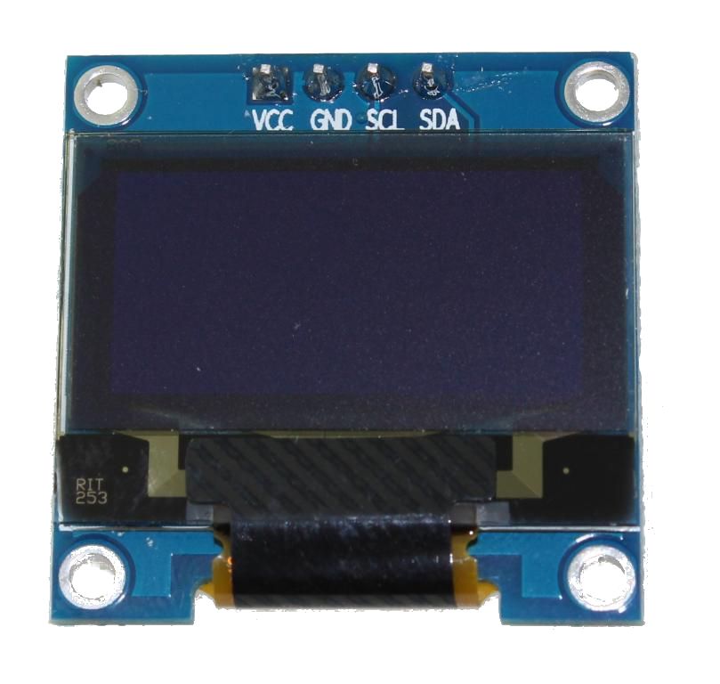
It is a 128×64 dot monochrome OLED screen module with I2C interface. It has several advantages compared to LCD screens, and we can highlight its high brightness, very good contrast, a wider viewing angle, and low consumption. of energy. It is compatible with Arduino Rasberry Pi and PIC microcontrollers among others. It works with logic levels from 3.3V to 5V and has a viewing angle greater than 160 degrees. Screen Size is 1.3 inches. It is powered with a voltage of 3.3V to 5V. It can be used in applications such as smart watches, MP3, thermometers, instruments, and various projects, etc.
Characteristics
Interface: I2C(3.3V / 5V logic level)
Resolution: 128 x 64
Angle of view: >160 degree
Display color: Blue
Display size: 1.3 inch
Driver IC: SH1106
Power supply: DC 3.3V~5V
Operating temperature: -20~70’C
Application: smart watch, MP3, thermometer, instruments, DIY projects, etc.
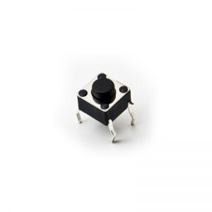
17 buttons
A socket for arduino pro micro
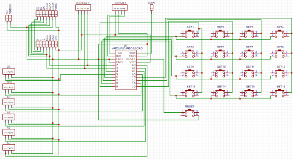
electronic diagram
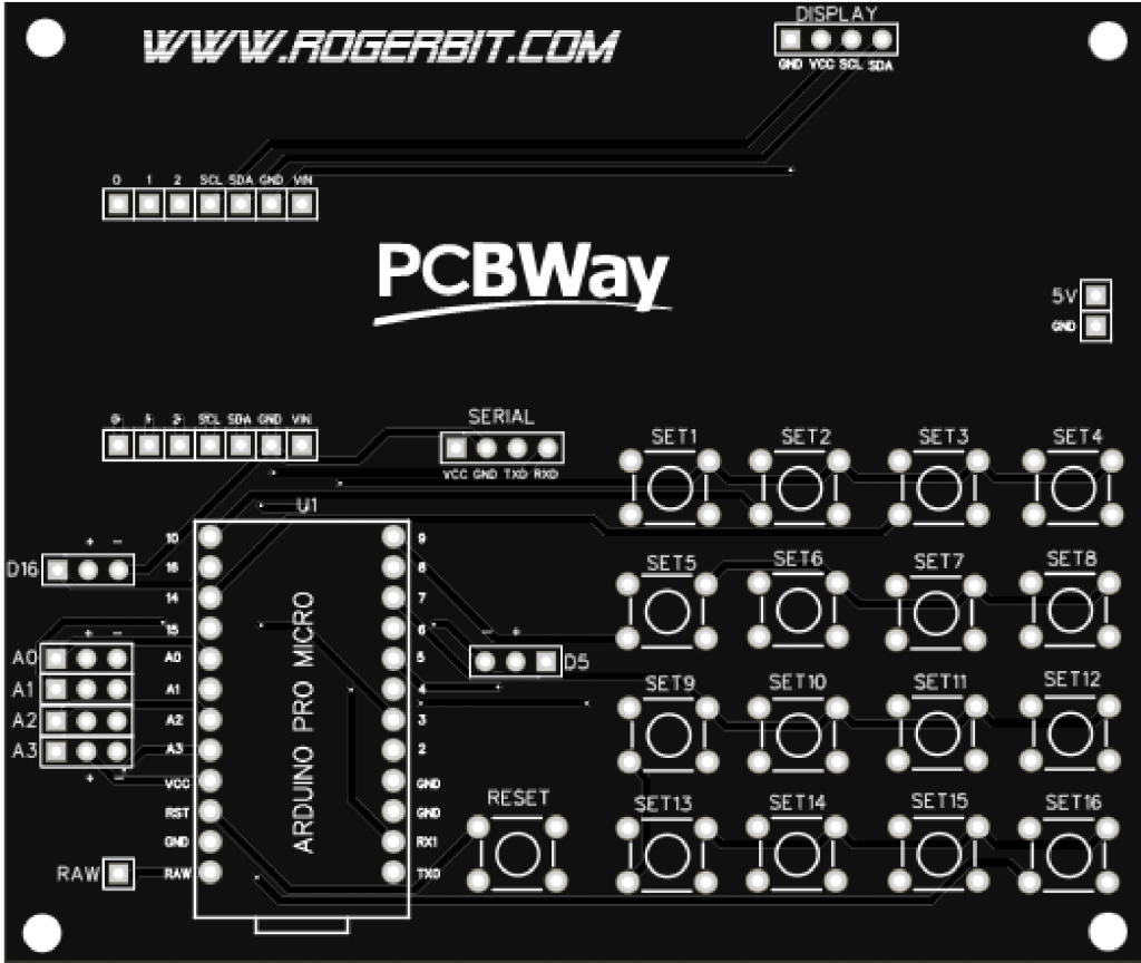
PCB
Source code
Download in https://rogerbit.com/wprb/2023/05/si5351/
Exploring the potential of the SI5351 module in electronic projects
*PCBWay community is a shared platform and we are not responsible for any design issues.


- Comments(0)
- Likes(2)
More by CarlosVolt Tutoriales
-
 How to make a water level meter with uln2803
In this tutorial we will see how to make a water level meter circuit with the built-in uln2803.The p...
How to make a water level meter with uln2803
In this tutorial we will see how to make a water level meter circuit with the built-in uln2803.The p...
-
 Emular mouse y teclado con arduino muy fácil
En este tutorial, aprenderemos cómo utilizar un Arduino para emular tanto un mouse como un teclado e...
Emular mouse y teclado con arduino muy fácil
En este tutorial, aprenderemos cómo utilizar un Arduino para emular tanto un mouse como un teclado e...
-
 Control of apc220 modules with smartphone and app
Controlling APC220 modules using a smartphone and an app involves connecting via a serial USB adapte...
Control of apc220 modules with smartphone and app
Controlling APC220 modules using a smartphone and an app involves connecting via a serial USB adapte...
-
 Exploring the potential of the SI5351 module in electronic projects
In this tutorial, you will dive into the depths of this amazing device and discover its limitless po...
Exploring the potential of the SI5351 module in electronic projects
In this tutorial, you will dive into the depths of this amazing device and discover its limitless po...
-
 Gas leak detector alarm system with arduino nano
In this tutorial we will see how to assemble a gas leak detector alarm system with arduino nano. We ...
Gas leak detector alarm system with arduino nano
In this tutorial we will see how to assemble a gas leak detector alarm system with arduino nano. We ...
-
 Build your own long-range weather station with Lora GPS anemometer module
In this tutorial we will see how to create a weather station, for places where there is no internet ...
Build your own long-range weather station with Lora GPS anemometer module
In this tutorial we will see how to create a weather station, for places where there is no internet ...
-
 Dual Synchronized Radio Frequency Control for Motor Lights and more
In this tutorial we will see how to do a synchronized radio frequency control, since one control can...
Dual Synchronized Radio Frequency Control for Motor Lights and more
In this tutorial we will see how to do a synchronized radio frequency control, since one control can...
-
 Object lifter with servo and Arduino Nano
Does your waist or back hurt when you bend down? So this invention, it's for you and it can help you...
Object lifter with servo and Arduino Nano
Does your waist or back hurt when you bend down? So this invention, it's for you and it can help you...
-
 8-channel dual light ignition system, infrared and pushbuttons
In this tutorial we will put together a dual light ignition system, since we can control the ignitio...
8-channel dual light ignition system, infrared and pushbuttons
In this tutorial we will put together a dual light ignition system, since we can control the ignitio...
-
 How to turn on lights with telegram and esp32 from anywhere in the world
In this tutorial we will see how to make a system that allows us to turn on lights with telegram, fr...
How to turn on lights with telegram and esp32 from anywhere in the world
In this tutorial we will see how to make a system that allows us to turn on lights with telegram, fr...
-
 Motion detector with light, esp32 and telegram notifications
In this tutorial we will see how to make a motion detector system, with a PIR sensor, a relay module...
Motion detector with light, esp32 and telegram notifications
In this tutorial we will see how to make a motion detector system, with a PIR sensor, a relay module...
-
 Alcoholimeter with MQ3 sensor and arduino nano (Includes printed circuit)
In this tutorial we will see how to make a breathalyzer, simple economical and easy to make. We’ll s...
Alcoholimeter with MQ3 sensor and arduino nano (Includes printed circuit)
In this tutorial we will see how to make a breathalyzer, simple economical and easy to make. We’ll s...
-
 GPS tracker without cellular network with LORA module
In this tutorial we will see how to make a tracker to GPS tracker, with LORA and Arduino module. We ...
GPS tracker without cellular network with LORA module
In this tutorial we will see how to make a tracker to GPS tracker, with LORA and Arduino module. We ...
-
 Build a meter with integrated circuit KA2284
KA2284 integrated circuit featuresHigh gain rectifier amplifier included (Gv = 26dB)Low radiation no...
Build a meter with integrated circuit KA2284
KA2284 integrated circuit featuresHigh gain rectifier amplifier included (Gv = 26dB)Low radiation no...
-
-
-
-
-
Open Source Very Large Stick - Freejoy & MMjoy2 breakout board
656 0 0 -
RF Control training board for students based on ESP32 C3
838 0 2


