


|
|
CR2032 coin cell |
x 1 | |
|
|
CR2032 coin cell Holder |
x 1 | |
|
|
slide Switch -11.6×4 mm |
x 1 | |
|
|
LED |
x 6 | |
|
|
1206 SMD package -6 (Any colour) |
x 1 | |
|
|
100K Resistor |
x 1 | |
|
|
1206 SMD Package |
x 1 |
The Light Badge
The Light Badge is an electronic kit which utilizes an LDR (light dependent resistor) to detect lowering light levels and light a LED once it gets dark.This is a great example of an LDR in action.

An LDR (light dependent resistor) or photoresistor is a resistor where the resistance decreases with the strength of the light.
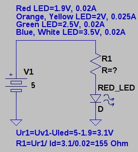
Schematics:

This is how the circuit works: When exposed to bright light, the photoresistor’s resistance is very low.It drops to around 20-30 KΩ.Current travels through the 100 KΩ resistor and then has 2 paths.It can either go through the base of the transistor or go through the photoresistor. The base of transistor to the collector has a resistance of around 400 KΩ.Current always takes the path of least resistance. When photoresistor is exposed to bright light, its resistance is about 20-30 kΩ, which is significantly less than the 400 kΩ of resistance the base of the transistor has.Therefore, most of the current will go through the photoresistor and very little will go to the base of the transistor. So the base of the transistor is bypassed, Thus, the transistor does not receive enough current to turn on and power on the LED.Thus the LED is off when there is lot of light in the surroundings.
When it is dark, photoresistor’s resistance becomes very high.It’s resistance goes up to 2 MΩ.This creates a very high resistance path, due to this, most of the current will go through the base of the transistor. Means that current does not go through the photoresistor when it is dark.
In the above circuit LDR and the 100 k resistor form a simple ‘potential divider’ circuit, where the middle point of the potential divider is fed to the base of the NPNtransistor. Therefore based on light intensity the brightness of LEDs will be changed.
Note: On the PCB I have represented anode of led with small white dotted silkscreen.
All the Project files are up on GitHub, go make!
This project is Certified with OSHWA (OSHWA UID IN000009)
The Light Badge
*PCBWay community is a shared platform and we are not responsible for any design issues.


- Comments(2)
- Likes(4)
- 7 USER VOTES
- YOUR VOTE 0.00 0.00

-
7design
-
9usability
-
8creativity
-
7content

-
8design
-
9usability
-
7creativity
-
7content

-
9design
-
9usability
-
9creativity
-
9content

-
8design
-
6usability
-
8creativity
-
9content

-
7design
-
8usability
-
7creativity
-
9content

-
8design
-
8usability
-
9creativity
-
8content

-
10design
-
10usability
-
10creativity
-
10content
More by Amal Mathew
-
 The Light Badge
 is an electronic kit which utilizes an LDR (light dependent resistor) to detect lowe...
The Light Badge
The Light Badge is an electronic kit which utilizes an LDR (light dependent resistor) to detect lowe...
-
 LED Flashlight Key chain
:It is a simple DIY (Do it yourself) kit to learn soldering and electronics....
LED Flashlight Key chain
LED Flashlight Key chain:It is a simple DIY (Do it yourself) kit to learn soldering and electronics....
-
 ATtiny LED Matrix Display Badge
Have you ever thought of making a badge-sized PCB that can display some letters, numbers, etc... or ...
ATtiny LED Matrix Display Badge
Have you ever thought of making a badge-sized PCB that can display some letters, numbers, etc... or ...
-
Open Source Very Large Stick - Freejoy & MMjoy2 breakout board
509 0 0 -
RF Control training board for students based on ESP32 C3
682 0 2 -
-
KINETIC COASTERS with a TWIST! Laser or 3D Print some DIY Magic
608 0 1 -
RPI - 8 IO PLC With ATTiny85 Watch Dog
533 0 1 -
Nintendo Famicom HVC-001 Controller Shells
627 0 1 -
COMMODORE 128 DIAGNOSTIC REV.785260 KEYBOARD DONGLE
596 0 4 -
COMMODORE 128 15KHz DISPLAY ADAPTER (C128 80 COLUMN ADAPTER)
803 1 7 -


